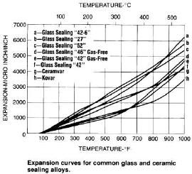
Glass sealed and controllled expansion alloys
*kovar alloy, ASTM F15, Nilo-K, UNS K94610 (FeNi29Co17),Chinese 4J29
* Specifications:ASTM F15; DIN 17745; S.E.W. 385; Werkstoff Nr. 1.3981; AFNOR NF A54-301
Similar Grades
|
Russia
|
U.S.A.
|
U.K.
|
Japan
|
France
|
Germany
|
|
29НК
|
Kovar
|
Nilo K
|
KV-1
|
Dilver P0
|
Vacon 12
|
|
29НК-ВИ
|
Rodar
Techallony Glasseal
29-17
|
Teleaseal
|
KV-2
KV-3
|
Dilver P1
|
Silvar 48
|
Grade & Chemical Composition (see Table
1)
Table
1 Grade & Chemical Composition
|
Grade
|
Chemical Composition (%)
|
|
C
|
P
|
S
|
Mn
|
Si
|
Cu
|
Cr
|
Mo
|
Ni
|
Co
|
Fe
|
|
≤
|
|
4J29
|
0.03
|
0.020
|
0.020
|
0.5
|
0.30
|
0.20
|
0.20
|
0.20
|
28.5~29.5
|
16.8~17.8
|
Bal
|
|
4J44
|
0.03
|
0.020
|
0.020
|
0.5
|
0.30
|
0.20
|
0.20
|
0.20
|
34.2~35.2
|
8.50~9.50
|
Bal
|
Notes:
1. The content of Al、Mg、Zr and Ti
should be no more than 0.10%,the
total content should be no more than 0.20%. Otherwise, the supplier’sPOand/or contract shall indicate clearly.
2. Under
condition that the average coefficient of the linear expansion meets the
requirements of the standard, the content of nickel and cobalt are allowed to
deviate from the stated range.
3. The shape and dimensions of the alloys are in
compliance with GB/T14985.
Mechanical Property (see table 2-table 4)
Table
2 Tensile Strength of Wire
|
Symbol
|
Status
|
Tensile Strength/MPa
|
|
R
|
Annealed
|
<585
|
|
1/4 I
|
1/4 hard
|
585~725
|
|
1/2 I
|
1/2 hard
|
655~795
|
|
3/4 I
|
3/4 hard
|
725~860
|
|
I
|
unannealed
|
>860
|
Table
3 Tensile Strength Of Strip
|
Symbol
|
Status
|
Tensile Strength/MPa
|
|
R
|
annealed
|
<570
|
|
1/4 I
|
1/4
unannealed
|
520~630
|
|
1/2 I
|
1/2
unannealed
|
590~700
|
|
3/4 I
|
3/4 unannealed
|
600~770
|
|
I
|
unannealed
|
>700
|
Table
4 Hardness of Deep Stamping Strips
|
State
|
Thickness
|
Hardness, Hv
|
|
Deep Stamping
|
>2.5mm
|
≤170
|
|
≤2.5mm
|
≤165
|
Physical Property (see Table 5
& Table 6)
Table 5 Coefficient of Linear Expansion
|
Grade
|
Heat Treatment of the Samples
|
Average Coefficient of Linear Expansion
|
|
20~300℃
|
20~400℃
|
20~450°C
|
|
4J29
|
Heat to temperature of 900±20℃ in the hydrogen, hold
for 1h; re-heat to 1100±20℃, hold for 15 min.; cooled to200℃ at a rate less than 5℃/min
|
|
4.6~5.2
|
5.1~5.5①
|
|
4J44
|
4.3~5.1
|
4.6~5.2
|
|
①Upper limit is 5.6 for transistors.
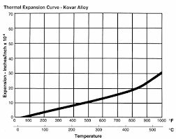
Table 6 Typical Coefficient of Linear Expansion
|
Grade
|
Average Coefficient of Linear Expansion
|
|
20~200℃
|
20~300℃
|
20~400℃
|
20~450℃
|
20~500℃
|
20~600℃
|
20~700℃
|
20~800℃
|
|
4J29
|
5.9
|
5.3
|
5.1
|
5.3
|
6.2
|
7.8
|
9.2
|
10.2
|
|
4J44
|
4.9
|
4.6
|
4.9
|
5.9
|
6.8
|
8.7
|
|
|
NOTE: The values in the table are for
reference only.
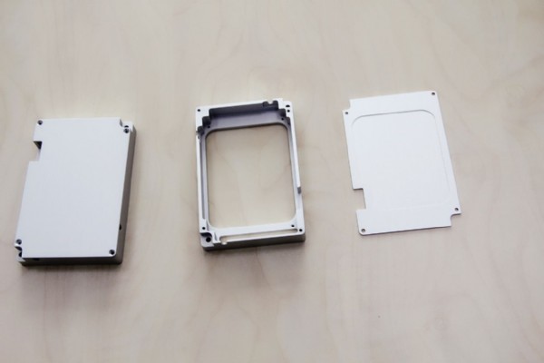
Usage:
It is applied to hard glass-to-metal seals.
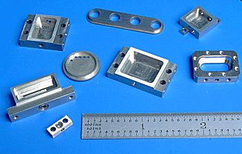
Applications
Kovar
alloy has been used for making hermetic seals with the harder Pyrex glasses and
ceramic materials.
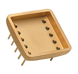
This alloy has found wide application in power tubes, microwave tubes,
transistors and diodes. In intergrated circuits, it has been used for the flat
pack and the dual-in-line package.
Preparation for Sealing
All
degreased, fabricated Kovar alloy parts should be degassed and annealed in a
wet hydrogen atmosphere. Atmosphere is to be made moist by bubbling the
hydrogen through water at room temperature. Care must be taken to prevent
surface carbon pickup. Furnace should have a cooling chamber provided with the
same atmosphere.
Heating should be conducted within the 1540/2010°F temperature range. Time at
temperature should be approximately two hours for lowest temperature to 20
minutes for the highest temperature. Parts should then be transferred to the
cooling zone and held until below 570°F, then removed.
An oxide film on the metallic part is preferred for metal-to-hard glass
sealing. The best oxide film is thin and tightly adhering. The film can be
produced by heating the parts to 1200/1290°F in regular ambient atmosphere for
a time sufficient to form a dark gray to slight brown oxide.
Workability
Forging
The principal precaution to observe in forging is to heat quickly and avoid
soaking in the furnace. Long soaking may result in a checked surface due to
absorption of sulfur from the furnace atmosphere and/or oxide penetration. A
forging temperature of 2000/2150°F is preferred.
Coolant
It is important to control heat build up, the major cause of warpage. A
suggested coolant would be Cool Tool. Cool Tool contains fatty esters to reduce
friction in the cutting zone and a refrigerant to remove the heat generated by
friction between the cutting tool and work place.
Tooling
T-15 Alloy, such as Vasco Supreme-manufactured by Vanadium Alloys Company. M-3
Type 2, such as Van Cut Type 2-manufactured by Vanadium Alloys Company. Congo
manufactured by Braeburn.
For machining with carbide tools, a K-6 manufactured by Kennemetal, Firthie HA
manufactured by Firth Sterling, or #370 Carboloy could be used, or a K2S
manufactured by Kennemetal, or Firthie T-04 manufactured by Firth Sterling
would be satisfactory. One thing of prime importance is that all feathered or
wire edges should be removed from the tools. They should be kept in excellent
condition by repeated inspection.
Turning
If steel cutting tools are used, try a feed of approximately .010" to
.012" per revolution and a speed as high as 35/FPM could probably be
attained. Some of the angels on the cutting tools would be as follows:
-
End cutting edge
angle -Approximately 7°
-
Nose radius
-Approximately .005"
-
Side cutting edge
angle -Approximately 15°
-
Back rake
-Approximately 8°
-
Side rake
-Approximately 8°
When cutting off
high speed tools are better than carbide tools, and a feed of approximately
.001" per revolution should be used. The cutting tools should have a front
clearance of about 7° and a fairly big tip--larger than 25° would be helpful.
Drilling
When drilling a 3/16" diameter hole, a speed of about 40/FPM could
possibly be used, and the feed should be about .002" to .0025" per
revolution, for a 1/2" hole, approximately the same speed could be used
with a feed of about .004" to .005" per revolution. The drills should
be as short as possible, and it is desirable to make a thin web at the point by
conventional methods. By conventional methods, we mean do not notch or make a
crank shaft grinding. It is suggested that heavy web type drills with nitrided
or electrolyzed surfaces be used. The hole, of course, should be cleaned
frequently in order to remove the chips, which will gall, and also for cooling.
The drill should be ground to an included point angle of 118° to 120°
Reaming
Reaming speeds should be half the drill speed, but the feed should be about
three times the drill speed. It is suggested that the margin on the land should
be about .005" to .010", and that the chamfer should be .005" to
.010" and the chamfer angle about 30°. The tools should be as short as
possible, and have a slight face rake of about 5° to 8°.
Tapping
In tapping, a tap drill slightly larger than the standard drill recommended for
conventional threads should be used, because the metal will probably flow into
the cut. It is suggested that on automatic machines, a two or three fluted
tapping tool should be used. For taps below 3/16", the two fluted would be
best. Grind the face hook angle to 8° to 10°, and the tap should have a
.003" to .005" chamfered edge. If possible, if binding occurs in the
hole in tapping, the width of the land may be too great, and it is suggested
that the width of the heel be ground down. Again, it is suggested that nitrided
or electrolyzed tools be used. Speed should be about 20/FPM.
|
High Speed Tool*
|
|
Turning
And
Forming
|
Cut-Off
Tool
|
1/16"
|
SFM
FEED
|
65
.0010
|
|
1/8"
|
SFM
FEED
|
67
.0012
|
|
1/4"
|
SFM
FEED
|
69
.0016
|
|
Tool
Width
|
1/2"
|
SFM
FEED
|
67
.0012
|
|
1"
|
SFM
FEED
|
63
.0010
|
|
1-1/2"
|
SFM
FEED
|
63
.0009
|
|
Drilling
|
Drill
Dia.
|
3/8"
|
SFM
FEED
|
43
.0030
|
|
3/4"
|
SFM
FEED
|
45
.0036
|
|
Reaming
|
Under 1/2"
|
SFM
FEED
|
57
.003
|
|
Over 1/2"
|
SFM
FEED
|
57
.0045
|
|
Threading
|
T.P.I
|
3-7
8-15
|
SFM
SFM
|
8
10
|
|
Over 16
|
SFM
|
16
|
|
Tapping
|
T.P.I
|
3-7
8-15
16-24
|
SFM
SFM
SFM
|
6
7
11
|
|
Over 25
|
SFM
|
16
|
|
Milling
|
|
SFM
FEED
|
35-70
.002-.005
|
|
Broaching
|
|
SFM
FEED
|
8-12
.001-.005
|
|
Turning
Single Point
& Box Tools
|
High Speed Tools
|
SFM
FEED
|
60-65
.0029-.0043
|
|
Carbide Tools
|
SFM
FEED
|
160-215
.025-.080
|
*When using carbide tools, surface
speed feet/minute (SFM) can be increased between 2 and 3 times over the high
speed suggestions. Feeds can be increased between 50 and 100%.
Note: Figures used for all metal
removal operations covered are average. On certain work, the nature of the part
may require adjustment of speeds and feeds. Each job has to be developed for
best production results with optimum tool life. Speeds or feeds should be
increased or decreased in small steps.
The information and data presented
herein are typical or average values and are not a guarantee of maximum or
minimum values. Applications specifically suggested for material described
herein are made solely for the purpose of illustration to enable the reader to
make his own evaluation and are not intended as warranties, either express or
implied, of fitness for these or other purposes.
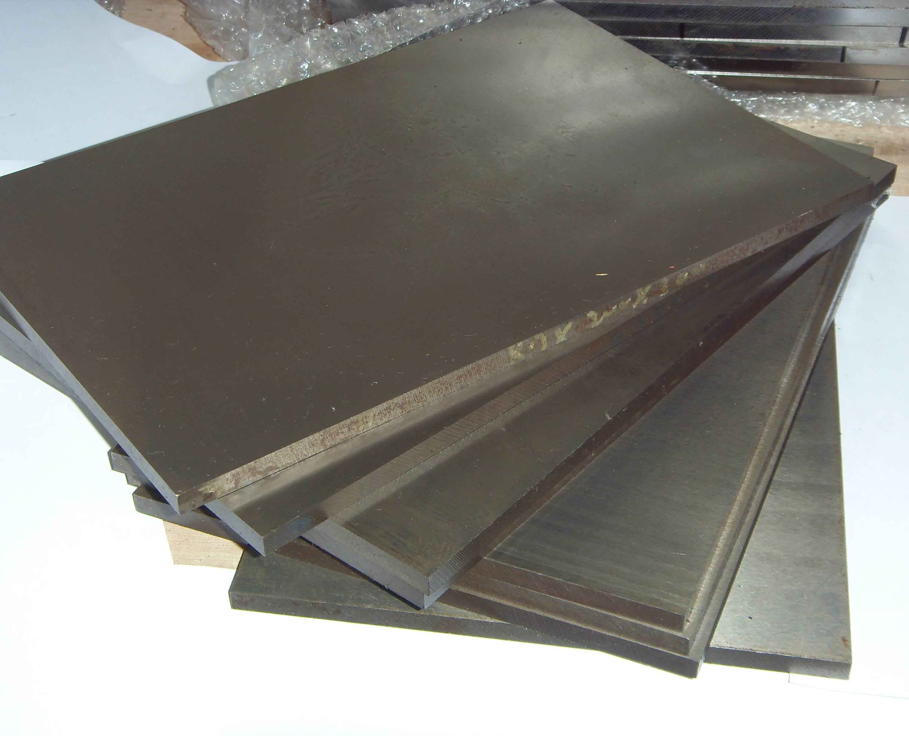
Specification:
Sheet/Plate, Bar/Rod/Wire/Coil,Capillary/Pipe/Tube
Size Range:
*Sheet---thickness 0.05mm~3.5mm, width:≤350mm,Condition: cold rolled, bright,
bright annealed
*Plate---thickness 3.5mm~40.0mm,width:≤300mm,Condition: cold rolled, hot
rolled, annealed
*Round Wire---Dia 0.05mm~Dia 5.0mm,Condition: cold drawn, bright, bright
annealed
*Flat Wire---Dia 0.5mm~Dia 5.0mm,length:≤1000mm,Condition:flat rolled, bright
annealed
*Bar---Dia 5.0mm~Dia 8.0mm,length:≤2000mm,Condition:cold drawn,bright, bright
annealed
Dia
8.0mm~Dia 32.0mm,length:≤2500mm,Condition:hot rolled,bright, bright annealed
Dia 32.0mm~Dia
180.0mm,length:≤1300mm,Condition:hot forging,peeled, turned, hot treated
Capillary---OD 8.0mm~1.0mm,ID 0.1mm~8.0mm,length:≤2500mm,Condition: cold drawn,
bright, bright annealed
Pipe---OD 120mm~8.0mm,ID 8.0mm~129mm,length:≤4000mm,Condition: cold drawn,
bright, bright annealed
Note: we could do any other
products with specified technical standard, say,
ASTM,SAE,DIN,S.E.W.,JIS,ISO,IEC,NF,BS,ΓОСТ.PLS contact us for more information:
Tel: +86-29-89396652 or e-mail us at: Sales@xaleipeng.com